
Manhole Cover Modeling
Our ultimate goal is to provide material properties to Mar-Bal Inc. that can be a substitute for their current sandwich configuration.However, the expense of manufacturing the same part for testing is costly and time consuming, finite element analysis is a convenient and suitable substitute for the experiment. Finite Element Analysis is a numerical way to solving engineering problems. This can be done by programs that one could generate geometry and test using various conditions.
This experiment uses Abaqus (Dassault Systèmes, Vélizy-Villacoublay, France) to model the manhole cover. The model is simplified as a quarter circle with a 20 inch radius (508 mm) with a thickness of 40 mm. The thickness is divided into three sections about 13.3 mm each. The quarter circle is subjected to symmetrical boundary conditions.
A force of 40 kips was delivered using a 10 inch radius cylinder concentric with the model. The model is restricted from moving parallel to the force at the circular edge. The materials are organized with the stiffest or a sandwich configuration at the center layer. The resultant load-displacement curve and stress profiles for the various configurations were plotted. The values derived from the modeling was then compared to the material properties of the flexural test.

FEA Geometry

Results
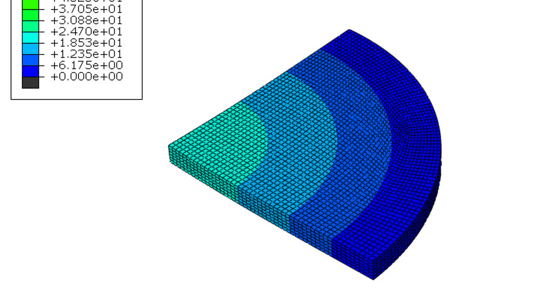
The results of the finite element analysis yielded a gradients of data for each of the configuration. For the samples involving Trim, two tests were ran for both kinds. Areas with the largest magnitude of data for the configurations were chosen. These results were plotted to further form a conclusion to the project. From the data stress profiles and force-displacement curves were derived from these specific points to analyze whether the material passed failed in the experiment.

Abaqus Results with cylinder
The Force displacement curve of the model shows the stiffness of the sandwich structure. Results of the model concluded that BMC-MAT-BMC was the stiffest material due to the high flexural modulus at the start of the simulation. However, the other materials are not too far behind, with BMC-SMC-BMC-SMC-BMC deviating the most out of the other six tested materials. This shows that Trim-Mat-Trim (1"x1") may be a viable candidate as a substitute to BMC-MAT-BMC.

FEA Force-Displacement Plot
The bulk of the results comes from the stress profile of the different configurations. The maximum principal stresses are compared to the breaking stress of the flexural stress. A table was formed which organizes the data into points based on their location, which the material is compared to the stresses experienced at that location. From the data, BMC-MAT-BMC and Trim-MAT-Trim (1"x1") did not exceed the failure stresses. This makes Trim-MAT-Trim (1"x1") a good substitute for the material Mar-Bal has. However, some materials may potentially meet requirements if more accurate geometry was created and tested. Potential candidates are BMC-SMC-BMC-SMC-BMC and Trim-Mat-Trim (1"x1/2").

Maximum Principal Stress Results

Displacement Results


